Lunar Rogowski Coil CTs enable key functionalities such as Partial Home Backup and the Power Control System (PCS). The coils are installed on the service disconnect conductors of a home to provide current measurements to the Lunar System.

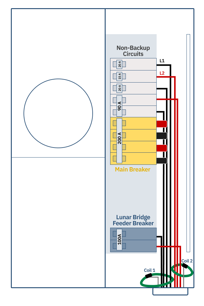
Terminate Coils at Lunar Bridge

Terminate the Coil leads to the labeled terminals Coil 1A/1B and Coil 2A/2B in the Bridge.
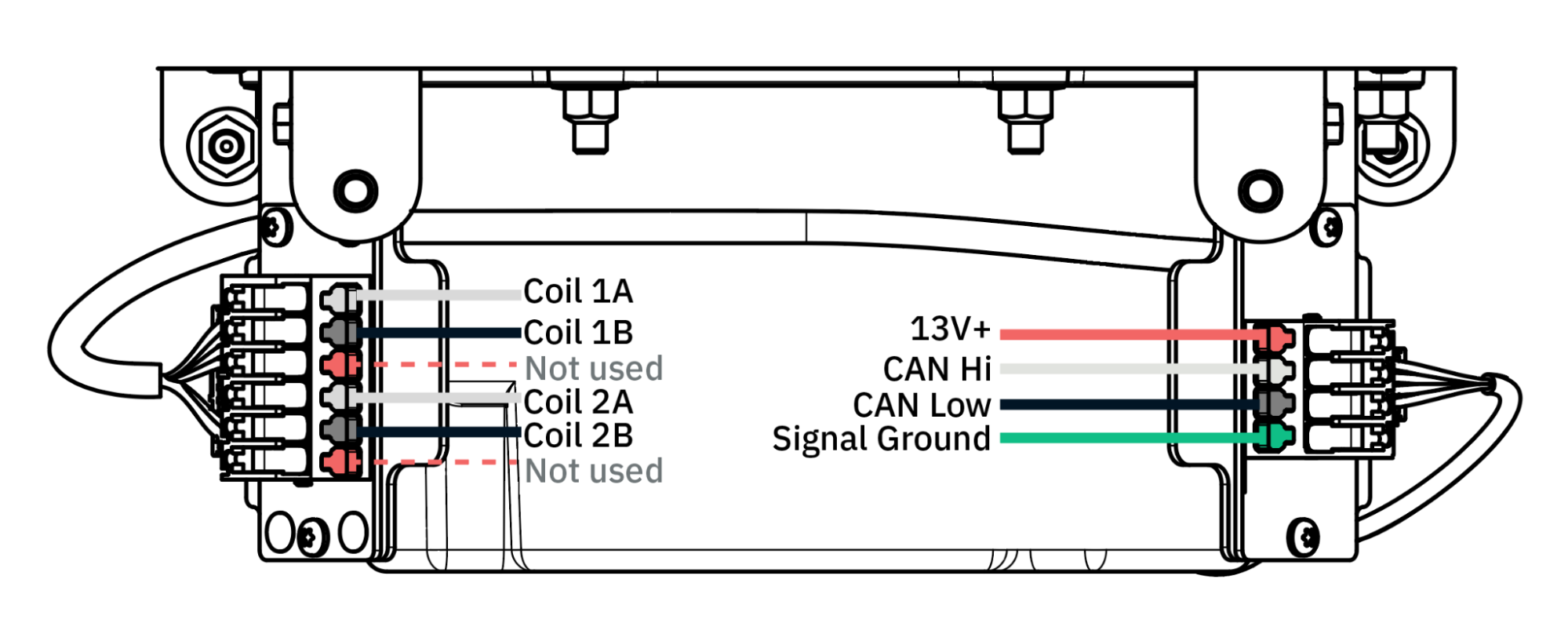
If a drain wire is present, do not splice or connect it to any conductor or terminal.
To extend coil free-end wires, use 12–24 AWG shielded wire (twisted or untwisted). The maximum extension length is 100 feet.

Coil Phase & Polarity

Use the Lunar Installer App to verify the phase (L1 vs. L2) and polarity (positive or negative current) of the coils. To correct the phase or polarity, adjust the wiring terminations at the Bridge:
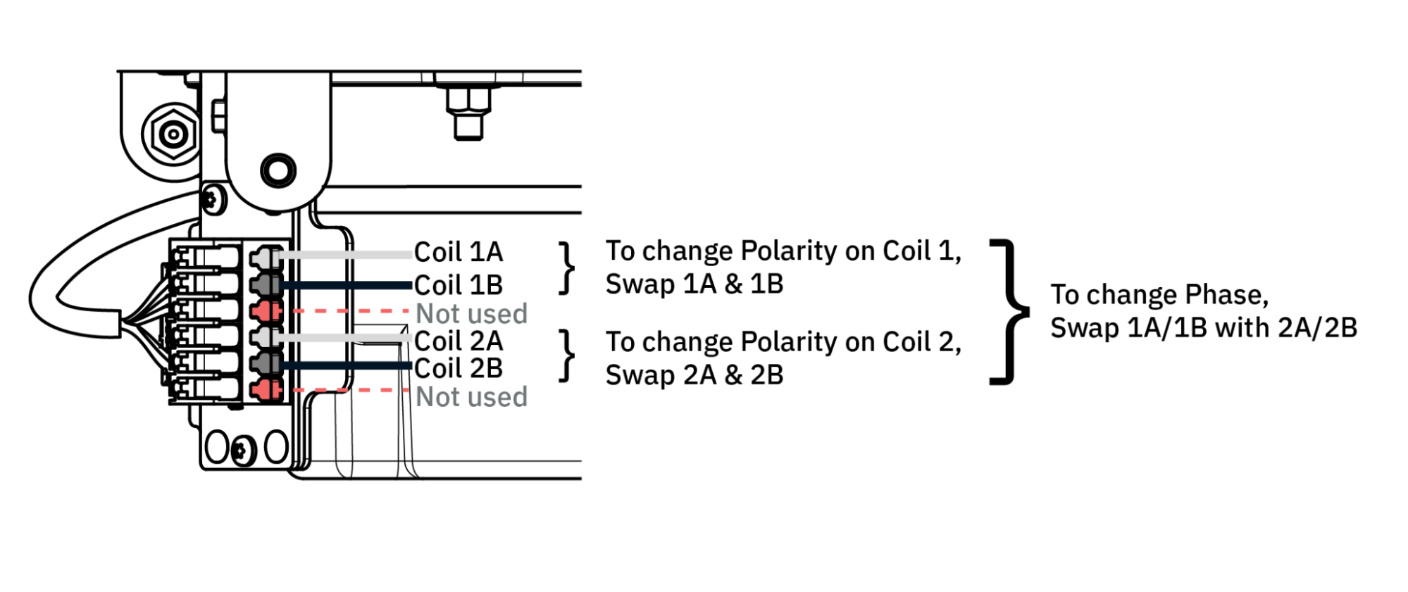
  • Coil Phase: Swap the terminations of Coil 1A and Coil 1B with Coil 2A and Coil 2B.
  • Coil Polarity: Swap the terminations of Coil 1A with Coil 1B, and swap the terminations of Coil 2A with Coil 2B.

Installing Coils on Branch Circuit Wires

If physical constraints (such as a 4-wire main breaker) prevent direct coils installation on service conductors, bundle the branch circuit wires instead.
1

Bundle Feeders

Bundle all non-backup load feeders and Lunar Bridge feeders within the coils.
2

Group Conductors

  • Group all L1 conductors through Coil 1.
  • Group all L2 conductors through Coil 2.
3

Verify Orientation

All wires must be oriented so that the current flow direction to or from the grid is the same.