Communication Range
Smart breakers communicate wirelessly with the Lunar Bridge or Lunar Meter Socket Adapter Controller (MSA Controller). They can be installed inside the Lunar Bridge or in any compatible EATON subpanel with maximum distances as detailed below:| Configuration | Maximum Distance to Lunar Bridge/MSA Controller |
|---|---|
| Free air | 75 ft (23 m) |
| Through 1 wall (wood / drywall) | 30 ft (9 m) |
| Through 1 wall (concrete / brick) | 10 ft (3 m) |
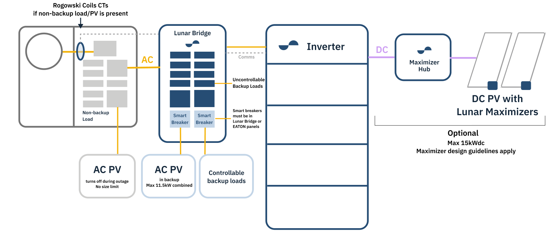
AC-Coupled PV Requirements
| Requirements | Description |
|---|---|
| Maximum AC PV in Backup | 11.5 kW combined of non-Lunar AC PV Examples (1) 1 x 7.6kW PV inverter and 1 x 3.8kW PV inverter (2) 3 x 3.8kW PV inverters Up to 8 smart breakers can be used to support multiple AC PV connections. For improved inverter-level monitoring and to prevent ground/arc faults from shutting down all PV, a dedicated smart breaker per AC PV system is recommended. A PV combiner subpanel with a single smart breaker is allowed, but not recommended. |
| Maximum AC PV in Non-Backup | No limit All non-backup loads and non-backup AC PV must be on the load side of the Lunar Rogowski Coils, along with the backup loads and backup AC PV. Refer to the Rogowski Coil (CTs) for the Lunar System Application Note. |
| Compatible PV Inverters | All CEC-listed models and makes. |
| Lunar DC PV Size | 0 - 15kWdc. DC PV is not required for the Lunar System. DC PV size is independent of AC PV size. Maximizer stringing rules apply. |
AC PV Metering
Smart breaker acts as a metering device for AC PV. No additional CT for PV circuits.Rogowski coils may still be required to monitor site import and export for partial home backup (i.e. AC PV in non-backup).
Line Side Tap
Install breaker between fused disconnect and AC PV, by following these steps:- Turning the fused disconnect OFF.
- Splicing the inverter output wires inside the inverter enclosure.
- Splicing there and back to an adjacent 2-space subpanel with a smart breaker.
Utility coordinated disconnect is not required. It does not touch or modify the tap, nor touch the wires between the tap and the fused disconnect.
Wiring Smart Breakers
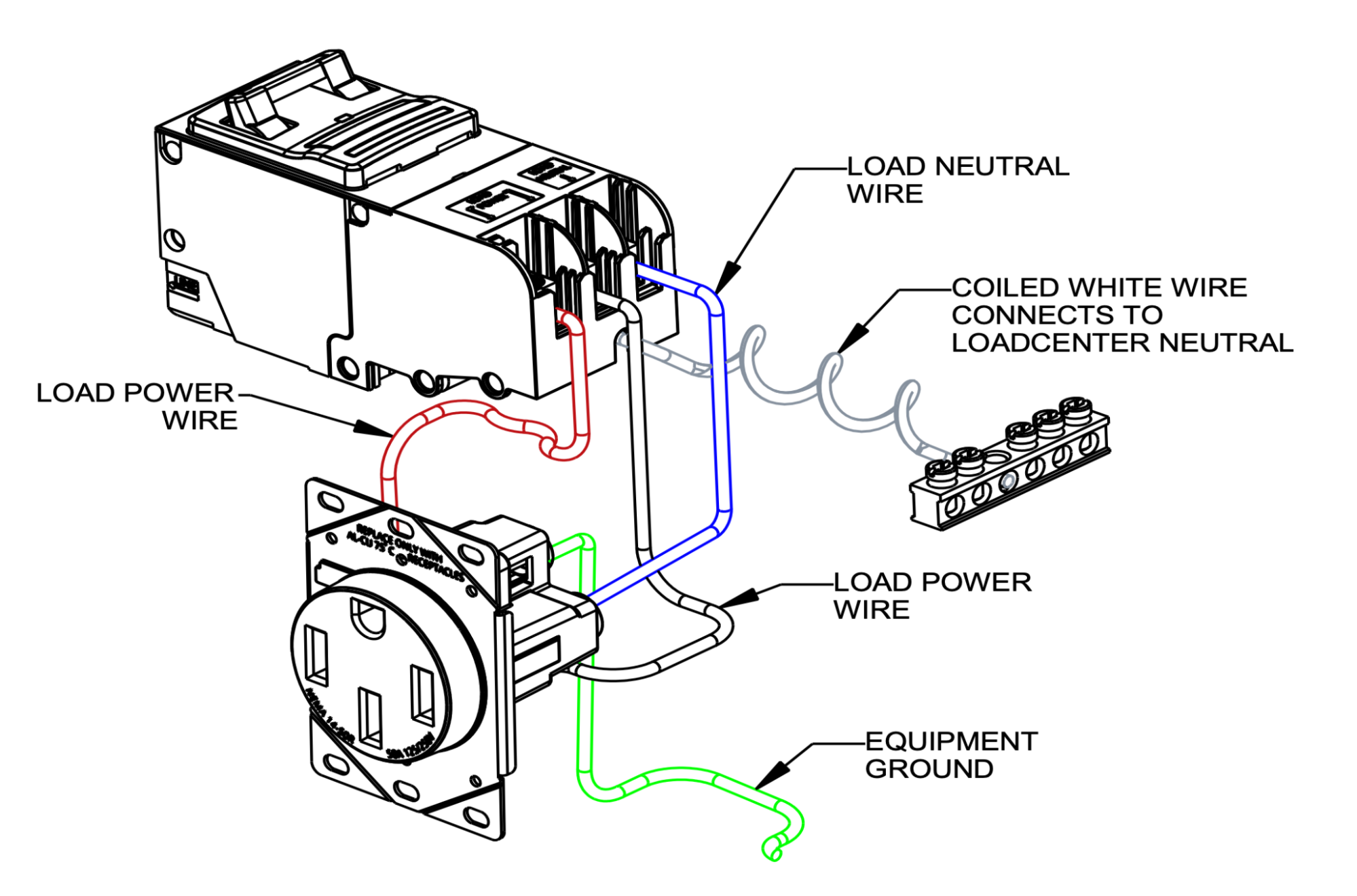
To avoid nuisance GFCI tripping, connect the load neutral wire directly to the breaker and the breaker’s neutral pigtail to the neutral bar.