Terminate the CAN communication cable’s drain wire (shielding conductor) at only one end — either the inverter or the Bridge.
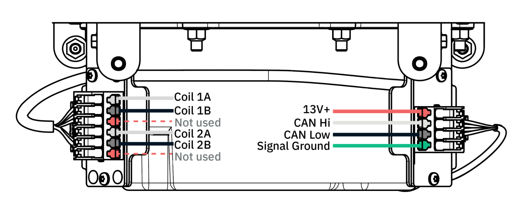
Rogowski coils (CT) wiring is required for partial home setup and Power Control System settings. See the Rogowski coils installation section for more details.